Quick Definition
The Membrane Electrode Assembly (MEA) is the electrochemically active core of a Proton Exchange Membrane (PEM) fuel cell, where hydrogen and oxygen react to generate electricity, water, and heat. It consists of a proton exchange membrane, catalyst layers, and gas diffusion layers, all working together to enable efficient electrochemical energy conversion.
Understanding MEA (Membrane Electrode Assembly) in PEM Fuel Cells
Fuel cell technology represents a significant advancement in the quest for cleaner and more efficient energy sources. Among the various types of fuel cells, the Proton Exchange Membrane (PEM) fuel cell stands out due to its potential for automotive applications and other mobile uses. Central to the operation of a PEM fuel cell is the Membrane Electrode Assembly (MEA). This article covers how the MEA works, the materials used in its construction, and its role in the overall function of the fuel cell.
Components of the MEA
Quick Comparison Table
| Component | Typical Material | Primary Role |
|---|---|---|
| Proton Exchange Membrane | Nafion (sulfonated fluoropolymer) | Conducts protons, blocks electrons and gases |
| Catalyst layers | Platinum or platinum alloy on carbon support | Facilitates hydrogen oxidation and oxygen reduction |
| Gas diffusion layers (GDL) | Carbon fiber paper or cloth, often PTFE-coated | Distributes gas, conducts electrons, manages water |
| Microporous layer (optional) | Carbon black + PTFE | Improves water management between catalyst and GDL |
Hydrogenergy supplies each of these individually, including membranes, catalysts, gas diffusion layers and complete MEAs, for research and industrial fuel cell applications.
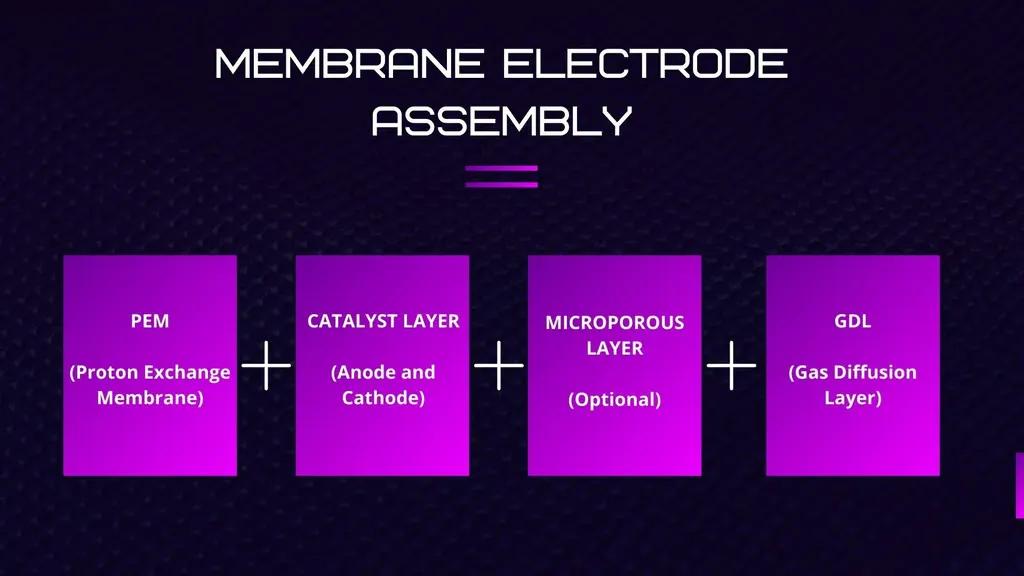
The MEA is a multi-layered structure composed of the following parts, covered in detail below: Proton Exchange Membrane (PEM), Catalyst Layers (Anode and Cathode), Microporous Layers (optional), and Gas Diffusion Layers (GDL).
The MEA is a multi-layered structure composed of the following parts:
- Proton Exchange Membrane (PEM)
- Catalyst Layers (Anode and Cathode)
- Microporous Layers (optional)
- Gas Diffusion Layers (GDL)
1. Proton Exchange Membrane (PEM)
The PEM is a polymer electrolyte membrane that allows protons (hydrogen ions) to pass through while being impermeable to gases like hydrogen and oxygen. The most commonly used material for PEMs is Nafion, a sulfonated tetrafluoroethylene-based fluoropolymer-copolymer.
Proton conductivity is essential, and Nafion achieves this through sulfonic acid groups that facilitate proton transfer. Chemical stability matters since the membrane must withstand the harsh oxidative environment within the fuel cell; Nafion's fluoropolymer backbone provides excellent chemical stability. Mechanical strength is also required, and while Nafion is mechanically robust, additional reinforcement such as expanded PTFE can enhance its strength further.
2. Catalyst Layers
On either side of the PEM are the catalyst layers, which consist of finely dispersed platinum or platinum-based alloys on carbon support. These layers facilitate the electrochemical reactions necessary for the fuel cell to generate electricity. Platinum is used for its excellent catalytic properties, sometimes alloyed with other metals like ruthenium or palladium to enhance performance and reduce poisoning from impurities. The carbon support is typically Vulcan XC-72, a type of carbon black providing a high surface area for platinum particles to disperse. The anode catalyst layer is where hydrogen gas is oxidized, and the cathode catalyst layer is where oxygen gas is reduced.
3. Gas Diffusion Layers (GDL)
The GDLs sit adjacent to the catalyst layers and serve multiple purposes. They facilitate gas transport, ensuring even distribution of hydrogen and oxygen to the respective catalyst layers. They conduct electrons, made from carbon fiber, away from the reaction sites to the external circuit. And they manage water produced at the cathode to prevent flooding and keep the membrane hydrated. Materials used include carbon fiber paper or cloth for high electrical conductivity and porosity, often with a Teflon (PTFE) coating applied to make it hydrophobic for water management.
4. Microporous Layers (Optional)
Some MEAs include a microporous layer between the catalyst layer and the GDL to improve water management, preventing excessive buildup and ensuring uniform reactant distribution. This is typically a thin layer of carbon black and PTFE mix, applied to provide additional porosity and hydrophobicity.
Working Principles of the MEA
The MEA is where the core reactions of the PEM fuel cell occur, in three main steps.
Hydrogen oxidation at the anode: hydrogen molecules enter the anode side, and the platinum catalyst facilitates separation into protons and electrons.
Proton transport through the PEM: the membrane allows protons to migrate from anode to cathode while blocking electrons, forcing them through an external circuit to create electric current.
Oxygen reduction at the cathode: oxygen molecules enter the cathode side, and the catalyst facilitates reaction of oxygen with incoming protons and electrons to form water.
The overall reaction combines hydrogen and oxygen to produce water, electricity, and heat.
Challenges in MEA Development
Despite their potential, PEM fuel cells face several ongoing challenges related to the MEA. Cost of catalysts remains a barrier since platinum is expensive. Durability is a concern, since the MEA must withstand operational stresses over time, including harsh chemical environments and mechanical stress. Water management is crucial to avoid both flooding and dehydration of the membrane. Thermal management is also needed, since heat generated during the reaction must be effectively managed to maintain optimal operating temperatures.
Advancements in MEA Technology
Ongoing research is focused on addressing these challenges. Catalyst innovations aim to reduce platinum loading and find alternative materials, including non-platinum catalysts based on transition metal carbides, nitrides, and oxides, and platinum-alloy catalysts with reduced platinum content but enhanced activity. Membrane improvements include alternatives like Aquivion with improved conductivity and durability, and composite membranes combining polymers with inorganic materials. Enhanced GDLs use advanced carbon materials like carbon nanotubes and graphene, along with improved hydrophobic treatments. Integrated water and thermal management is advancing through microfluidic channels for precision water and thermal regulation and improved heat exchanger designs.
Future Outlook
The future of PEM fuel cells and their MEAs is promising, especially given the push for sustainable energy solutions. Key areas of focus include cost reduction through material innovations and economies of scale, performance enhancement through continuous improvements in MEA design and materials, and mass adoption as the technology matures across transportation and portable power applications.
Conclusion
The Membrane Electrode Assembly is genuinely the electrochemical heart of every PEM fuel cell, and understanding its individual components (the membrane, catalyst layers, gas diffusion layers, and optional microporous layer) is essential for anyone specifying, testing, or troubleshooting fuel cell systems. As research continues to address cost, durability and water management challenges, MEA technology remains one of the most active areas of fuel cell development.
Need help with your hydrogen project?
Our engineers respond within 24 hours with a recommendation.
Hydrogenergy Applications Engineering Team
Applications Engineering · Hydrogenergy Technologies
Hydrogenergy's applications engineering team designs and supplies hydrogen systems for research labs and industry across India — from components to complete commissioned setups.