Quick Definition
Sizing a fuel cell means choosing a stack rating that delivers your required net power for the full runtime. It accounts for balance-of-plant losses, aging, and peak loads. It also fixes how much hydrogen you must store or supply.
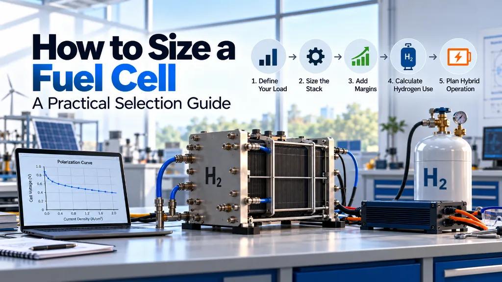
A fuel cell stack rated at 1 kW does not hand 1 kW to your load. Fans, pumps, compressors, and controllers take their share first. Most sizing mistakes start here, when a datasheet figure is treated as usable power. This guide walks from your real load to a stack rating and a hydrogen budget. Every step uses a formula you can check yourself.
Start with net load, not stack rating
Write down three numbers before you compare any PEM fuel cell datasheet. First, the continuous power your load draws. Second, the peak power and how long it lasts. Third, the runtime you need between hydrogen refills.
A steady 500 W load for eight hours is a very different problem from a 500 W average with 2 kW spikes. The first points to a stack sized close to the average. The second needs either a much larger stack or a battery to cover the peaks.
Also note the voltage your load expects. A DC-DC converter usually sits between the stack and the load, and it adds its own small loss.
Convert net power into stack power
Net power is what reaches your load. Gross power is what the stack produces. The gap is balance-of-plant consumption: air supply, cooling, humidification, purge valves, and controls.
The size of that gap depends on the design. Open-cathode stacks use a fan instead of a compressor. In one 1 kW open-cathode study, fan power fell to about 2% of stack power at higher load currents. Closed-cathode systems use air compressors, and published figures put compressor draw at up to 15 to 20% of gross power. Our comparison of open cathode and closed cathode fuel cells explains why the two behave so differently.
Gross stack power (kW) = Net load (kW) / (1 minus BOP fraction)
For a 1 kW net load and a 15% BOP share, the stack must produce about 1.18 kW.
Plan for aging and peak demand
Stack voltage drifts down over its life. End of life is often defined as a voltage or power loss somewhere between 10 and 20%. If you size to the day-one figure, the system will miss its target as the stack ages.
A planning margin of 10 to 20% on top of gross power is a sensible starting point.
Rated stack power = Gross stack power x (1 + margin)
The margin also helps efficiency. PEM cell voltage is higher at lower load, so a stack running below its rated power is usually more efficient and gentler on the membrane.
Calculate hydrogen consumption
Hydrogen use follows directly from current. Each amp through one cell consumes about 0.007 standard liters of hydrogen per minute. For a whole stack, the cell count and current combine into a single formula.
Hydrogen flow (slpm) = 0.00698 x Gross power (W) / Cell voltage (V)
Rated cell voltage for a PEM stack is commonly 0.6 to 0.7 V. Stack efficiency on a lower heating value basis is roughly cell voltage divided by 1.25, so 0.65 V means about 52%. A polarization curve from a fuel cell test station shows the real cell voltage at your operating current. That beats trusting a nominal figure.
Real systems use slightly more hydrogen than the formula predicts. Purging and fan power both add losses. In one 1 kW open-cathode test under a UAV load profile, net efficiency was about 52% against 58% for the stack alone.
Hydrogen needed (Nm3) = Flow (Nm3/h) x Runtime (h) x (1 + reserve)
One kilogram of hydrogen is about 11.1 Nm3. A reserve of 5 to 10% covers purge losses and measurement error. For the supply side, the options are compressed hydrogen cylinders or an on-site electrolyzer sized to cover this daily consumption.
Choose the right fuel cell type
For most labs, backup systems, and drones, PEM is the practical default. The table shows why, and where the other types fit.
Choose the right fuel cell type
| Factor | PEM | SOFC | Alkaline |
|---|---|---|---|
| Operating temperature | About 60 to 100 °C | About 500 to 1,000 °C | About 60 to 90 °C |
| Typical electrical efficiency | Roughly 40 to 60% | Up to about 60%, with 80 to 90% total in combined heat and power | Quoted at 50 to 70%, varies widely |
| Start-up | Fast | Slow, can take up to an hour | Fast |
| Load following | Good | Poor | Good |
| Best fit | Mobile, backup, UAV, lab systems | Steady baseload, heat recovery | Niche uses, needs CO2-free air |
SOFC systems reward steady loads. They struggle with frequent starts and fast load changes. If your duty cycle is stop and start, PEM is the safer choice.
Pair the stack with a battery
A battery lets you size the stack for average power instead of the peak. The stack runs steadily and efficiently. The battery covers short spikes and recharges in the gaps.
Battery energy (Wh) >= (Peak power minus Stack net power) x Peak duration (h)
Add margin for usable depth of discharge. Hybrid systems like this are common in drone fuel cell designs, where takeoff and climb need far more power than cruise.
Even steady systems often keep a small battery. The stack's fans and valves need power at start-up, before the stack can supply it.
A worked example
A lab needs 1 kW net for 6 hours from a PEM stack. The BOP share is 15% and the aging margin is 15%.
- Gross power: 1.0 kW / (1 minus 0.15) = 1.18 kW
- Rated stack power: 1.18 kW x 1.15 = 1.35 kW, so choose a stack in the 1.4 to 1.5 kW class
- Hydrogen flow at 0.65 V per cell: 0.00698 x 1,180 / 0.65 = 12.7 slpm, or about 0.76 Nm3/h
- Hydrogen for 6 hours: 0.76 x 6 = 4.6 Nm3
- With a 10% reserve: about 5.0 Nm3, or roughly 0.45 kg
The supply must hold at least 5 Nm3. This is a simplified estimate. Confirm it against a vendor's polarization curve and your actual load profile.
Common sizing mistakes
- Treating the datasheet rated power as the power that reaches the load
- Skipping the aging margin, then missing the target a year later
- Sizing the stack for peak power instead of using a battery
- Comparing efficiency figures without checking whether they use lower or higher heating value, which differ by about 18%
- Forgetting that PEM stacks need clean hydrogen and a regulated supply pressure
- Fixing the stack rating before knowing the runtime, so the hydrogen supply ends up undersized
Conclusion
Fuel cell sizing works best in one direction: start from the net load, add balance-of-plant losses and an aging margin, then work out the hydrogen your runtime requires. A battery turns a peak-sized stack into an average-sized one, and a polarization curve replaces assumptions with real cell voltage. For labs, pilot systems, and UAV projects, Hydrogenergy's fuel cell range includes air-cooled and liquid-cooled PEM stacks. The team can help match a configuration to your load profile.
Need help with your hydrogen project?
Our engineers respond within 24 hours with a recommendation.
Hydrogenergy Applications Engineering Team
Applications Engineering · Hydrogenergy Technologies
Hydrogenergy's applications engineering team designs and supplies hydrogen systems for research labs and industry across India — from components to complete commissioned setups.