Quick Definition
Sizing an electrolyzer means matching its hydrogen output capacity (measured in kg/day, Nm3/h, or MW of input power) to your actual demand. It also means matching capacity to your available power supply and required purity and pressure, so you're neither underbuilding for peak demand nor paying for capacity you'll never use.
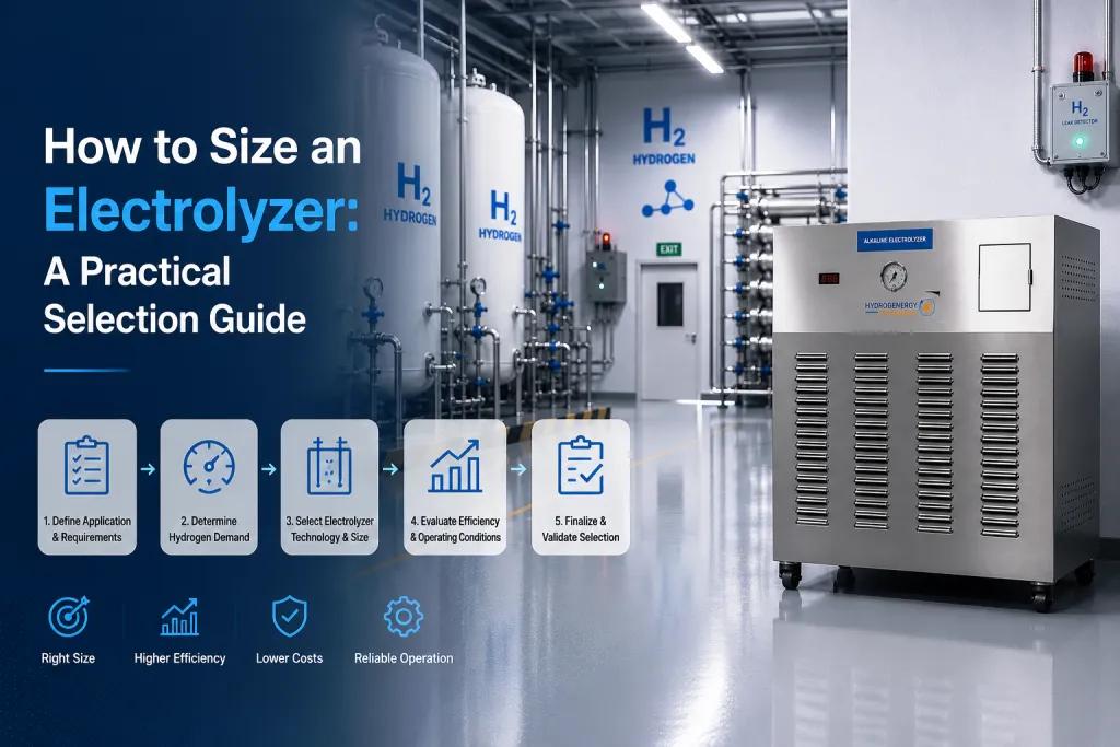
Start with demand, not capacity
Most sizing mistakes happen because someone starts with a electrolyzer spec sheet instead of their own consumption numbers. Before comparing MW ratings, get three numbers pinned down:
- How much hydrogen do you need, and over what time window (kg/day, or a peak kg/hour if there's a filling or batch process involved)
- Is that demand constant, or does it spike (a refuelling window, a batch reactor charge, a shift changeover)
- What's your production window, meaning how many hours a day the electrolyzer will actually run
A plant that needs 100 kg/day of hydrogen delivered over 20 hours of operation has very different capacity requirements than one that needs the same 100 kg delivered in a 4-hour burst.
Convert demand into the right units
Electrolyzer datasheets are usually rated in Nm3/h (normal cubic meters per hour, at standard temperature and pressure) or in kg/h, alongside a power rating in kW or MW. The two are linked through the specific energy consumption of the stack. Based on typical figures reported by sources like IEA and NREL for commercially available PEM and alkaline systems, this falls in the range of 50 to 55 kWh per kg of hydrogen produced, or roughly 4.5 to 5 kWh per Nm3. Balance-of-plant loads (compression, cooling, purification, control systems) add on top of the stack figure, so the number on your utility bill will run higher than the stack-only spec.
It's worth being precise about which number you're using. Stack specific energy consumption (stack SEC) only covers the electrolysis reaction itself. System specific energy consumption (system SEC) includes the stack plus compression, cooling, water treatment, and controls. It's the system SEC figure that should actually be used when sizing your electrical infrastructure and utility connection, not the stack-only number.
A rough working method: divide your daily hydrogen requirement in kg by your planned daily run hours to get a kg/h production rate, then multiply by the specific energy consumption to estimate the input power draw in kW.
The core sizing formula:
- Production rate (kg/h) = Daily hydrogen demand (kg/day) / Planned run hours per day
- Estimated input power (kW) = Production rate (kg/h) x Specific energy consumption (kWh/kg)
Where specific energy consumption typically falls between 50 and 55 kWh/kg for commercial PEM and alkaline stacks, before balance-of-plant load is added.
If your datasheet gives capacity in Nm3/h instead of kg/h, convert using the approximate relationship 1 kg H2 = 11.1 Nm3 (at standard temperature and pressure), so:
- Production rate (Nm3/h) = Production rate (kg/h) x 11.1
This lets you compare a demand figure calculated in kg against a supplier's Nm3/h-rated datasheet directly.
Working backward: sizing from available power instead of demand
If you're planning around a fixed power budget instead, such as a renewable installation with a known capacity, the same formula works in reverse:
- Hydrogen production (kg/h) = Available power (kW) / System specific energy consumption (kWh/kg)
For example, 500 kW of available power at a system SEC of 52 kWh/kg gives an estimated production rate of roughly 9.6 kg/h. From there, multiply by your expected operating hours per day to get a daily output figure. Remember to discount for renewable intermittency, electrolyzer turndown limits, and any battery buffering in the system before treating that number as a reliable daily average rather than a peak figure.
This power-to-hydrogen direction is the more relevant calculation for solar or wind-connected projects, where the power supply is the fixed constraint and hydrogen output is the variable being solved for. It's the reverse of a grid-connected plant, where demand is fixed and power draw is calculated from it.
Match electrolyzer type to your power source
This is where sizing and technology selection overlap, and it's the single biggest source of oversized or undersized systems.
If your electrolyzer will run on a stable grid connection, both alkaline and PEM systems handle steady-state operation well, and sizing is mostly a straightforward capacity calculation.
If you're powering the system directly from solar or wind without full grid backup, the picture changes. PEM electrolyzers respond quickly to fluctuating input and tolerate a wide turndown range, which suits the variability of renewable generation. Alkaline systems are typically slower to ramp and have a narrower stable operating band. A variable renewable supply may call for a battery buffer to smooth input, or for a bank of smaller alkaline units brought online in stages rather than one large unit running at partial, unstable load.
Account for purity and output pressure
Sizing isn't only about volume. Two systems rated for the same Nm3/h output can differ meaningfully in what you actually get delivered:
- Purity requirements vary by application. Research and calibration work may call for higher purity than industrial process use, and hitting a tighter purity spec sometimes means adding downstream purification, which itself draws power and needs to be factored into your sizing math.
- Output pressure affects downstream compression needs. An electrolyzer with higher native output pressure reduces the compression stage required before storage, which changes both your capacity requirement and your capital cost elsewhere in the system.
Get both numbers from your process requirements before comparing capacity specs across suppliers, since a lower-priced unit at low output pressure can end up costing more once compression is added.
Build in turndown and redundancy
Two practical additions on top of a pure capacity number:
- Turndown ratio: if your demand fluctuates, check how low a percentage of rated capacity the electrolyzer can run at while staying stable. A unit that can only run efficiently between 60 and 100 percent of rated output isn't a good fit for a process with wide demand swings.
- Redundancy and maintenance downtime: a single electrolyzer sized exactly to peak demand has no buffer for scheduled maintenance or an unplanned outage. Larger installations often use multiple smaller stacks rather than one large unit, so one can be serviced while others keep producing.
Comparison: PEM vs alkaline vs AEM for sizing decisions
AEM is worth a brief note before the table, since it's often listed alongside PEM and alkaline without context on where it actually stands. AEM aims to offer PEM-like dynamic response with less reliance on precious-metal catalysts. But it has less commercial deployment history and fewer long-term field references than PEM or alkaline, so sizing decisions involving AEM should lean more heavily on direct vendor data than on general figures.
| Factor | PEM | Alkaline | AEM |
|---|---|---|---|
| Turndown range | Wide, handles low partial load well | Narrower, less stable at low load | Improving, still less proven at scale |
| Response to variable input (solar/wind) | Fast ramp, well suited | Slower ramp, benefits from buffering | Fast ramp, but fewer long-term field references |
| Typical footprint for a given capacity | More compact | Larger footprint per unit output | Compact, similar to PEM |
| Output pressure | Often higher native pressure | Typically lower, more external compression needed | Varies by manufacturer |
| Best sizing approach | Single unit sized to peak, using turndown for variability | Multiple smaller units staged to match load | Case by case, confirm vendor turndown data directly |
A worked example
Say a lab or pilot facility needs 20 kg of hydrogen per day, delivered over a 16-hour operating window, at 99.999 percent purity for calibration use, with no renewable variability to worry about since it's grid-connected.
- Production rate needed: 20 kg / 16 h = 1.25 kg/h
- Estimated stack power draw: 1.25 kg/h x ~52 kWh/kg = roughly 65 kW, before balance-of-plant losses
- Add balance-of-plant and purification load, and a working estimate lands somewhere in the 75 to 90 kW range depending on the specific purification train required
- Since the load is steady and grid-connected, either PEM or alkaline can work technically. The purity requirement and lab footprint constraints usually tip the decision toward PEM for installations at this scale.
This is a simplified estimate. Actual sizing should be confirmed against a specific vendor's efficiency curve and your facility's real power availability.
Common sizing mistakes
- Sizing to nameplate capacity of downstream equipment instead of actual measured or projected demand
- Ignoring balance-of-plant power draw and sizing only to the stack's rated consumption
- Choosing alkaline for a highly variable renewable-only supply without a buffer, then finding the system struggles at partial load
- Skipping purity and pressure requirements until after a unit is already selected, leading to expensive downstream retrofits
- No redundancy plan, so a single scheduled maintenance event stops hydrogen production entirely
Conclusion
Electrolyzer sizing comes down to getting your real demand numbers right before you start comparing capacity specs, then layering in power source, purity, pressure, turndown, and redundancy on top of that baseline. A unit that looks right on a datasheet can still be the wrong fit once your actual operating conditions are accounted for. If you're working through a spec for a research lab, pilot line, or industrial process, Hydrogenergy's electrolyzer range spans PEM and alkaline systems across a range of capacities, and the team can help match a configuration to your demand profile and power setup.
Need help with your hydrogen project?
Our engineers respond within 24 hours with a recommendation.
Hydrogenergy Applications Engineering Team
Applications Engineering · Hydrogenergy Technologies
Hydrogenergy's applications engineering team designs and supplies hydrogen systems for research labs and industry across India — from components to complete commissioned setups.